Flip in Remote Solar Farm Work: What Flight Overlap Really
Flip in Remote Solar Farm Work: What Flight Overlap Really Decides
META: A field-driven case study on using Flip for remote solar farm imaging, with practical insight on overlap design, elevation accuracy, building and equipment occlusion, and antenna handling under electromagnetic interference.
Remote solar sites have a way of exposing weak flight planning fast.
On paper, a photovoltaic plant looks simple: long rows, repeatable geometry, broad access roads, open sky. In the field, the job is trickier. Elevation consistency matters more than many teams expect. Transformer yards create localized electromagnetic interference. Inverter stations, cable trenches, perimeter structures, and occasional service buildings interrupt clean lines of sight. And if the mission is meant to support mapping, progress documentation, and asset review in one outing, the aircraft has to deliver more than pretty footage.
That is where Flip becomes interesting.
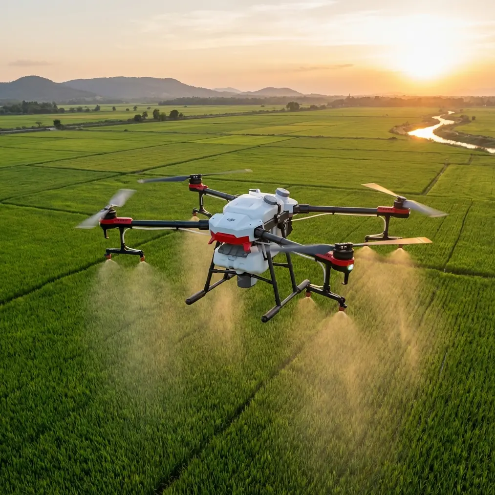
I approached this project as both an imaging professional and a field operator. The assignment was a remote solar farm delivery and documentation mission, with the client needing reliable visual coverage for construction verification and model generation. Not a cinematic vanity flight. A working dataset. The kind that has to hold up when engineers start checking whether surfaces, grades, and equipment corridors look the way the plans said they would.
The central lesson was not about speed or camera style. It was about overlap, occlusion, and the way small technical choices upstream decide whether the final model is usable.
Why remote solar farm work punishes casual flight planning
A common misconception is that large open industrial sites are forgiving. They are not. Solar farms often stretch across terrain with subtle changes in relief. Those changes may appear minor on the ground, yet they show up immediately when teams need dependable elevation interpretation across access lanes, mounting rows, drainage paths, and service pads.
The reference material makes a sharp point that still gets underestimated in day-to-day drone work: in aerial photogrammetry, planimetric accuracy is usually easier to achieve than elevation accuracy. Height accuracy is the stricter challenge. It depends on a combination of GSD, the base-to-height ratio, and image point measurement precision.
That matters operationally for Flip because a remote solar mission is usually judged on whether the dataset can support interpretation, not merely whether it looks complete. If the vertical component is weak, a site can appear visually “covered” while still being less useful for grading checks or 3D context.
The source also notes a practical distinction between traditional analog imagery and digital aerial imagery: image point coordinate measurement precision is assumed at 1/2 pixel for traditional imagery and 1/3 pixel for digital imagery, expressed as k=2 versus k=3. That sounds academic until you are trying to understand why a compact digital platform can still produce strong elevation results despite other geometric constraints. Better image measurement precision gives digital capture a real edge.
For a Flip operator in the field, this translates into something simple: the value of the mission is not just in collecting enough photos, but in collecting the right photos with geometry that supports height reconstruction.
The site problem no one fixes by adding more cameras
This solar farm had long repetitive panel corridors with scattered vertical obstructions near electrical infrastructure. The temptation in these situations is to assume that more viewing angles from the same broad perimeter will solve gaps. The reference material warns against that thinking with an excellent example: if an area between two buildings is completely blocked by their height and the aircraft never flies over that zone, adding more cameras still will not capture the occluded space. The result is geometric sticking or model adhesion between structures.
Swap those two buildings for site structures at a solar plant and the principle remains unchanged.
At our location, the most vulnerable areas were not the panel arrays themselves. They were the transitions around inverter stations, maintenance sheds, and fenced utility clusters. If Flip did not pass over those spaces with sufficient overlap, the model would bridge or smear geometry where clean separation was required. That kind of defect is more than cosmetic. It can mislead stakeholders about clearances, circulation paths, or the true shape of installed assets.
This is why I treat occlusion as a route-design issue, not a post-processing issue.
The overlap settings that actually made the mission work
A lot of field teams still default to overlap presets without asking what the site geometry demands.
The source provides a useful baseline: in practical orthophoto operations, forward overlap is often set at 80% and side overlap at 60% to protect image accuracy. But it also makes clear that for UAV oblique photogrammetry, 60% side overlap is obviously insufficient. Algorithmically, 66.7% is cited as a theoretical recommendation, and for UAV oblique work in areas without high-rise buildings and with relatively small terrain variation, both forward and side overlap are recommended at no less than 70%.
That threshold became my minimum planning logic for Flip on this job.
Even though a solar farm is not a downtown canyon, remote energy sites still include enough vertical interruptions and enough mission value in 3D interpretation that running lower overlap would have been a false economy. We planned with the understanding that 70% is not a luxury number in this kind of work. It is a protective floor when pitch, roll, and real-world site irregularity start affecting the image block.
In cleaner row sections, Flip handled the repetitive coverage pattern efficiently. In the infrastructure zones, I pushed for denser redundancy. The reference notes that in dense built environments, overlap can be designed as high as 80% to 90% to improve collection quality. A solar farm is not a dense urban block, but the logic still applies in localized clutter. Around electrical compounds and mixed-height support structures, increasing redundancy reduced the risk of missing slivers of space that later become reconstruction failures.
The tradeoff is also clearly stated in the source: more overlap means more data, and more data lowers processing efficiency. That is real. Processing time grows. Sorting and quality control become heavier. But for a remote deployment, a slightly larger dataset is far cheaper than returning to site because one equipment cluster fused into an unusable mesh.
Handling electromagnetic interference without losing the mission
This site also brought a field condition that product pages rarely explain well: electromagnetic interference around power infrastructure.
Near transformer and inverter areas, control link behavior can become less predictable. In practice, one of the simplest ways to stabilize the operation is old-fashioned operator discipline. I adjusted antenna orientation deliberately as the aircraft moved relative to the control position, instead of assuming a static setup would be fine for the whole route. That sounds minor. It is not.
The narrative around “obstacle avoidance” often dominates discussions about remote industrial flying, but signal awareness deserves equal billing. Obstacle avoidance helps protect the aircraft around structures and service poles. Antenna adjustment helps preserve command reliability when nearby equipment is generating a noisy radio environment. They solve different problems, and on a remote solar site you may need both on the same leg of the mission.
Flip’s utility here was not in flashy automation alone. It was in giving me enough confidence to keep the capture geometry disciplined while managing interference zones like an operator, not a spectator.
Why the aircraft had to fly over the target area, not just around it
One line from the reference should be taped above every mission-planning monitor: to obtain complete image information for a given area, the UAV must fly over that area.
This is obvious once said out loud, yet many remote-site operators still design around the edges of sensitive infrastructure, hoping angled capture will fill in the blanks. On our solar farm mission, I resisted that shortcut. The critical corridors had to be crossed. The aircraft needed true overhead relationship to the target spaces, not just oblique visibility from the side.
That choice paid off in two ways.
First, it protected continuity in the photogrammetry block. Second, it improved the practical storytelling value of the project documentation. A client reviewing panel field progression, service access, and spacing issues can understand a dataset faster when the geometry is coherent. This is where tools like D-Log and Hyperlapse can support broader project communication, but only after the technical capture is secure. A cinematic pass through the site is useful for stakeholder updates. It cannot rescue weak mapping geometry.
Flip beyond mapping: what actually mattered on a solar assignment
I know the keyword cloud around Flip tends to drift toward Subject tracking, ActiveTrack, QuickShots, and visual creativity. Those functions have their place. For a remote solar project, though, their value is secondary and situational.
ActiveTrack or subject tracking can help during non-mapping documentation segments, especially when following maintenance vehicles on access routes for progress footage. QuickShots are fine for short client-facing social edits. But the core mission at a site like this is disciplined aerial collection with enough overlap and enough positional common sense to preserve model integrity.
That is why the most useful “feature” on this project was not a mode. It was the ability to execute a careful flight plan consistently.
The source also mentions that when tall structures exceed one quarter of the flight height, one remedy is to increase overlap and add cross-flight lines for redundant observation. Solar farms rarely present skyscraper-like obstacles, but the principle is still valuable around elevated equipment and service structures. If a section begins to produce hidden faces or uncertain geometry, the answer is not guesswork. It is more observation from a better route pattern.
The data-versus-efficiency decision every remote team has to make
There is always pressure to fly lean. Remote jobs carry logistics, weather uncertainty, and limited windows. Nobody wants excess images.
But the source is right to frame overlap as inseparable from data volume. Higher overlap expands the dataset. Processing slows down. Storage and transfer demands rise. On a remote solar farm, that becomes a strategic decision rather than a technical footnote.
I would rather bring back a heavier but defensible dataset than a lightweight one that collapses around critical structures.
The reason is simple: the cost of insufficiency compounds. If engineers cannot trust the model, they start requesting selective rechecks. If visual gaps appear around infrastructure, the client loses confidence in the whole deliverable. If geometry sticks where there should be separation, someone has to explain whether the defect comes from the site or from the capture.
Good overlap prevents those conversations.
A practical field takeaway for Flip operators
If you are deploying Flip for remote solar farm delivery, inspection support, or documentation, the smartest move is to stop treating overlap as a generic preflight setting.
Treat it as the project’s structural backbone.
Start from the reality that vertical accuracy is the harder problem. Respect the minimum 70% forward and side overlap guidance for UAV oblique work in relatively simple terrain, and be ready to go denser around electrical yards, structures, and any area where occlusion might create false geometry. Remember that typical 80% forward and 60% side overlap may be serviceable for standard orthophoto work, but it can fall short when the mission demands stronger 3D reconstruction. And never assume angled views can replace true overflight of the area you need to capture.
On this assignment, those decisions mattered more than any headline feature. They turned Flip from a convenient camera platform into a reliable field tool.
If you are planning a similar operation and want to compare flight design logic for remote energy sites, you can message the field team here and discuss overlap strategy, interference handling, and route planning before you go out.
That is the difference between flying a site and actually covering it.
Ready for your own Flip? Contact our team for expert consultation.