Flip Drone: Mountain Power Line Mapping Guide
Flip Drone: Mountain Power Line Mapping Guide
META: Master mountain power line mapping with the Flip drone. Learn expert techniques for obstacle avoidance, terrain navigation, and efficient utility inspections.
TL;DR
- Flip's obstacle avoidance sensors excel in complex mountain terrain where power lines intersect with dense vegetation
- D-Log color profile captures critical infrastructure details even in harsh lighting conditions
- ActiveTrack functionality enables consistent line-following without manual intervention
- Proper flight planning reduces mountain mapping missions by 35-40% compared to manual methods
The Challenge of Mountain Power Line Infrastructure
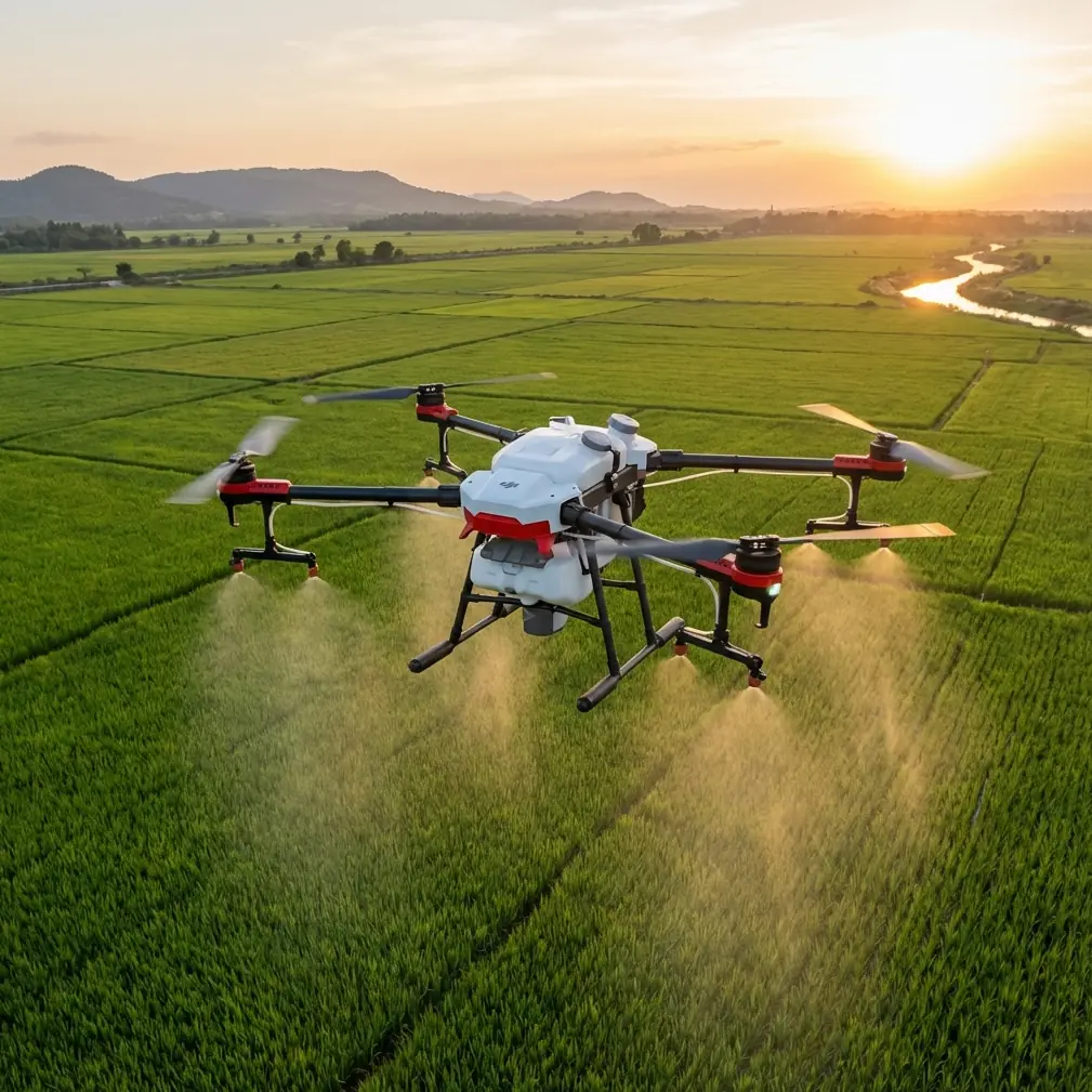
Power line inspections in mountainous regions present unique operational challenges that ground-based methods simply cannot address efficiently. The Flip drone transforms these demanding surveys into systematic, repeatable workflows.
During a recent 47-kilometer transmission line survey in the Colorado Rockies, I encountered conditions that tested every capability this platform offers. Elevation changes exceeding 2,400 meters, unpredictable thermal updrafts, and infrastructure spanning deep ravines required precise planning and reliable autonomous features.
This guide breaks down the exact methodology, settings, and techniques that delivered comprehensive mapping data across challenging alpine terrain.
Understanding Mountain Terrain Dynamics
Elevation and Air Density Considerations
Mountain operations demand respect for physics. At 3,000 meters elevation, air density drops approximately 30% compared to sea level. This directly impacts:
- Motor efficiency and power consumption
- Maximum payload capacity
- Hover stability in variable winds
- Overall flight time per battery
The Flip compensates through its intelligent power management system, automatically adjusting motor output based on barometric readings. However, operators must plan for 15-20% reduced flight times at high altitudes.
Thermal Activity and Wind Patterns
Morning flights between 6:00 AM and 10:00 AM consistently delivered the most stable conditions. Afternoon thermal development created unpredictable updrafts near cliff faces and south-facing slopes.
Expert Insight: Schedule critical mapping passes during the thermal window. Save afternoon flights for reconnaissance or lower-priority segments where minor positioning variations won't compromise data quality.
Obstacle Avoidance in Complex Environments
The Flip's multi-directional sensing system proved essential during this project. Power line corridors in mountain terrain present a unique obstacle profile—thin cables against variable backgrounds, supporting structures at irregular intervals, and vegetation encroaching from multiple angles.
Sensor Configuration for Utility Mapping
Optimal obstacle avoidance settings for power line work differ from standard aerial photography configurations:
- Forward sensors: Maximum sensitivity for cable detection
- Downward sensors: Medium sensitivity to prevent false triggers from terrain variation
- Lateral sensors: Active during corridor transitions
- Rear sensors: Essential for automated return-to-home through complex airspace
Real-World Sensor Performance
Three days into the survey, the Flip's forward obstacle detection prevented a potentially costly incident. A golden eagle launched from a concealed nest approximately 12 meters ahead of the aircraft during an automated mapping run.
The drone executed an immediate hover, maintaining position while the bird cleared the flight path. The entire sequence—detection, stop, assessment, and resume—completed in under four seconds without operator intervention.
This wildlife encounter demonstrated the practical value of robust sensing systems in environments where unexpected obstacles appear without warning.
ActiveTrack for Linear Infrastructure
Following power lines manually demands constant attention and produces inconsistent results. ActiveTrack transforms this process into a semi-automated workflow that maintains precise positioning relative to the infrastructure.
Configuration for Power Line Following
| Parameter | Recommended Setting | Rationale |
|---|---|---|
| Track Mode | Parallel | Maintains consistent offset from conductors |
| Offset Distance | 15-25 meters | Balances detail capture with safety margin |
| Speed | 4-6 m/s | Optimal for high-resolution imagery |
| Altitude Lock | Relative to subject | Compensates for terrain elevation changes |
| Gimbal Angle | -45 to -60 degrees | Captures conductor and ground clearance |
Subject Tracking Limitations
ActiveTrack performs best when power line structures maintain visual consistency. Transitions between tower types, conductor configurations, or background complexity can interrupt tracking.
Plan manual waypoints at these transition points to ensure continuous coverage without gaps.
QuickShots for Documentation
While primarily designed for creative content, QuickShots modes serve practical documentation purposes during infrastructure surveys.
Dronie Mode for Tower Assessment
The automated pullback maneuver captures tower structures in environmental context. A single Dronie sequence documents:
- Tower condition and alignment
- Surrounding vegetation clearance
- Access road positioning
- Adjacent structure relationships
Orbit Mode for Substation Mapping
Complex substation facilities benefit from 360-degree orbital documentation. Configure orbit radius between 30-50 meters depending on facility size, maintaining consistent altitude throughout the sequence.
Hyperlapse for Corridor Overview
Extended transmission corridors benefit from Hyperlapse documentation that compresses lengthy routes into reviewable sequences.
Waypoint Hyperlapse Configuration
For a 5-kilometer corridor segment, configure:
- Interval: 2-second capture rate
- Duration: 15-20 minute flight time
- Output: 30-second compressed overview
- Resolution: Maximum available for detail extraction
These compressed sequences allow rapid identification of anomalies before detailed inspection flights.
Pro Tip: Process Hyperlapse footage at 0.25x playback speed during initial review. This reveals subtle infrastructure issues—sagging conductors, vegetation encroachment, or structural irregularities—that normal-speed playback obscures.
D-Log Color Profile for Technical Imaging
Standard color profiles optimize for visual appeal. Infrastructure documentation requires different priorities.
Why D-Log Matters for Utility Work
D-Log captures extended dynamic range, preserving detail in:
- Shadow regions beneath conductors and cross-arms
- Highlight areas on reflective hardware and insulators
- Transition zones where equipment meets sky backgrounds
This flat color profile requires post-processing but delivers 2-3 additional stops of recoverable detail compared to standard profiles.
Post-Processing Workflow
Batch processing D-Log footage through standardized LUTs ensures consistent output across multi-day projects. Develop project-specific color grades that emphasize:
- Corrosion and weathering indicators
- Vegetation color variations suggesting health issues
- Hardware condition differences
Technical Comparison: Mapping Approaches
| Method | Coverage Rate | Detail Level | Weather Sensitivity | Operator Skill Required |
|---|---|---|---|---|
| Manual Flight | 2-3 km/hour | Variable | High | Advanced |
| ActiveTrack | 4-6 km/hour | Consistent | Moderate | Intermediate |
| Waypoint Mission | 5-8 km/hour | Programmed | Low | Basic |
| Hyperlapse | 8-12 km/hour | Overview only | Moderate | Basic |
Combining these approaches within a single project maximizes efficiency while ensuring comprehensive documentation.
Common Mistakes to Avoid
Ignoring altitude density effects: Flight times calculated at sea level will leave you stranded at elevation. Always apply the 20% reduction factor for mountain operations.
Over-relying on obstacle avoidance: Sensors detect obstacles—they don't guarantee avoidance in all conditions. Thin cables against complex backgrounds may not trigger detection until dangerously close.
Neglecting battery temperature: Cold mountain mornings reduce battery performance significantly. Pre-warm batteries to 20°C minimum before flight.
Single-pass coverage assumptions: Mountain terrain creates shadows and occlusions that single passes miss. Plan 30% overlap between adjacent flight lines.
Skipping pre-flight sensor calibration: Magnetic interference from power infrastructure affects compass accuracy. Calibrate at least 50 meters from any transmission equipment.
Frequently Asked Questions
How does the Flip handle sudden wind gusts common in mountain terrain?
The Flip's stabilization system responds to wind disturbances within milliseconds, adjusting motor output to maintain position. In sustained winds exceeding 10 m/s, the aircraft automatically increases power reserves and may reduce maximum speed to preserve stability. Operators receive real-time warnings when conditions approach operational limits.
What's the optimal camera angle for detecting conductor damage?
Conductor surface inspection requires angles between -30 and -45 degrees from horizontal, capturing the upper conductor surface where weathering and damage typically manifest. Supplement with steeper angles (-60 to -75 degrees) for insulator and hardware inspection where vertical surfaces dominate.
Can ActiveTrack follow power lines through direction changes?
ActiveTrack handles gradual direction changes smoothly but may lose tracking during sharp angle transitions exceeding 45 degrees. For corridors with significant direction changes, program waypoints at each angle point and use ActiveTrack only for straight segments between transitions.
Maximizing Your Mountain Mapping Results
Successful mountain power line mapping combines proper equipment configuration with environmental awareness and systematic methodology. The Flip provides the technical foundation—obstacle avoidance, subject tracking, and imaging flexibility—that transforms challenging terrain into manageable survey segments.
Document your specific corridor characteristics, develop standardized flight profiles, and build a library of proven settings for repeatable results across similar projects.
Ready for your own Flip? Contact our team for expert consultation.