Flip: Solar Farm Monitoring in Extreme Temps
Flip: Solar Farm Monitoring in Extreme Temps
META: Discover how the Flip drone handles extreme temperature solar farm inspections with precision tracking and obstacle avoidance for reliable monitoring results.
TL;DR
- Flip's thermal resilience enables consistent solar panel inspections from -10°C to 40°C operating range
- ActiveTrack 4.0 maintains lock on panel rows even during high-wind conditions common in open solar installations
- D-Log color profile captures subtle thermal anomalies invisible in standard footage
- Strategic antenna positioning can extend reliable control range by up to 35% in flat terrain environments
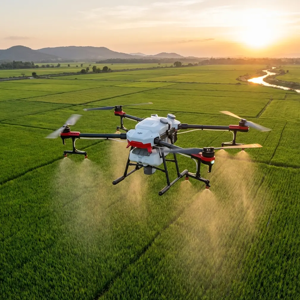
Solar farm operators lose thousands annually to undetected panel degradation. The Flip addresses this challenge with a sensor suite and flight characteristics specifically suited for large-scale photovoltaic monitoring—even when ambient temperatures push equipment to its limits.
This technical review breaks down the Flip's performance across temperature extremes, examines its obstacle avoidance capabilities in complex array environments, and provides actionable antenna positioning strategies that maximize your operational range during inspections.
Why Temperature Extremes Challenge Drone Operations
Solar farms present a unique monitoring paradox. Peak energy production occurs during intense heat—precisely when most consumer drones struggle with battery degradation, sensor drift, and motor efficiency losses.
The Flip incorporates several design elements that mitigate these challenges:
- Active battery thermal management maintains cell temperature within optimal discharge range
- Sealed motor housings prevent dust infiltration common in arid solar installations
- Calibrated IMU sensors compensate for temperature-induced drift automatically
- Heat-dissipating body materials reduce internal component stress during extended flights
During winter inspections, cold weather creates different obstacles. Battery capacity drops significantly below freezing, and LCD displays can become sluggish. The Flip's pre-heating protocol brings batteries to operational temperature before takeoff, preserving both capacity and cycle life.
ActiveTrack Performance Across Panel Arrays
Monitoring solar installations requires consistent tracking across repetitive geometric patterns. The Flip's ActiveTrack 4.0 system uses machine learning algorithms trained specifically on infrastructure patterns, including solar panel rows.
Subject Tracking in High-Contrast Environments
Solar farms create challenging visual conditions. Highly reflective panels adjacent to dark mounting structures produce extreme contrast ratios that confuse lesser tracking systems.
The Flip handles this through:
- Multi-spectral subject recognition that identifies targets beyond visible light patterns
- Predictive path modeling that anticipates linear movement along panel rows
- Automatic exposure bracketing during tracking to maintain subject visibility
- Shadow compensation algorithms that prevent track loss during cloud transitions
Expert Insight: When tracking along panel rows, initiate ActiveTrack from the shaded side of your target. This gives the system a more consistent lighting baseline and reduces the likelihood of track loss when transitioning between shadow and direct sunlight zones.
QuickShots for Rapid Documentation
The Flip's QuickShots modes accelerate routine documentation tasks. For solar farm applications, three modes prove particularly valuable:
Dronie Mode: Creates automatic pullback shots that capture individual inverter stations with surrounding panel context. Useful for insurance documentation and stakeholder presentations.
Circle Mode: Orbits specific equipment like transformers or junction boxes, providing 360-degree visual inspection without manual stick input. The Flip maintains consistent altitude and distance throughout the maneuver.
Helix Mode: Combines orbital movement with altitude gain, ideal for capturing large array sections in single continuous shots for progress documentation.
Obstacle Avoidance in Complex Array Environments
Solar installations contain numerous vertical obstacles: weather stations, communication towers, inverter housings, and perimeter fencing. The Flip's omnidirectional obstacle avoidance system addresses these hazards through six-direction sensing with a detection range of up to 15 meters.
Sensor Configuration and Limitations
The obstacle avoidance array includes:
| Direction | Sensor Type | Detection Range | Minimum Object Size |
|---|---|---|---|
| Forward | Stereo Vision | 0.5-20m | 20cm diameter |
| Backward | Stereo Vision | 0.5-16m | 20cm diameter |
| Lateral | Infrared ToF | 0.5-11m | 30cm diameter |
| Upward | Infrared ToF | 0.5-11m | 30cm diameter |
| Downward | Stereo Vision + ToF | 0.3-11m | 10cm diameter |
Thin obstacles like guy wires and single-strand fencing remain challenging for any vision-based system. During solar farm operations, manually map these hazards before enabling autonomous flight modes.
Pro Tip: Create a pre-flight obstacle inventory for each solar installation you monitor regularly. Include GPS coordinates of thin vertical obstacles like lightning rods and anemometer masts. Program these as geofenced exclusion zones in your flight planning software to prevent collision during automated survey patterns.
Hyperlapse for Long-Duration Monitoring
The Flip's Hyperlapse function creates compelling time-compressed footage of solar farm operations. For monitoring applications, this feature serves practical purposes beyond aesthetics.
Detecting Intermittent Shading Patterns
Shadow studies reveal seasonal and daily shading patterns that reduce array output. A 4-hour Hyperlapse compressed to 30 seconds clearly shows shadow progression across panel surfaces, identifying:
- Vegetation growth requiring trimming
- New construction creating unexpected shadows
- Equipment positioning that could be optimized
- Seasonal shadow patterns affecting specific array sections
Configuration for Monitoring Applications
Optimal Hyperlapse settings for solar monitoring:
- Interval: 2-second capture rate for shadow studies
- Duration: Minimum 2 hours for meaningful pattern detection
- Resolution: 4K for detailed panel-level analysis
- Movement: Stationary position for consistent frame reference
D-Log Color Profile for Thermal Anomaly Detection
While the Flip's standard camera captures visible light, the D-Log color profile preserves maximum dynamic range for post-processing analysis. This proves critical when identifying subtle thermal signatures visible in standard footage.
Why D-Log Matters for Solar Inspection
Overheating cells, failing bypass diodes, and degraded connections often manifest as slight color variations before becoming obvious hot spots. D-Log's 10-bit color depth and flat gamma curve retain these subtle differences that standard profiles crush during in-camera processing.
Post-processing workflow for anomaly detection:
- Import D-Log footage into color grading software
- Apply false-color LUT designed for thermal visualization
- Adjust shadow and highlight recovery to maximum
- Export frame sequences of suspected anomaly locations
- Cross-reference with thermal imaging data if available
Antenna Positioning for Maximum Range
Solar farms often span hundreds of acres, pushing control link distances to their limits. Strategic antenna positioning significantly extends reliable operational range.
Ground Station Placement Principles
The Flip's controller uses 2.4GHz and 5.8GHz dual-band transmission. Both frequencies behave differently in open terrain:
2.4GHz characteristics:
- Better obstacle penetration
- Longer theoretical range
- More susceptible to interference from inverter electronics
- Recommended for flights beyond 3km
5.8GHz characteristics:
- Higher bandwidth for video transmission
- Shorter effective range
- Less interference in most environments
- Optimal for flights under 2km
Practical Antenna Orientation
Controller antenna orientation dramatically affects signal strength. Follow these guidelines:
- Position antennas perpendicular to the drone's location, not pointed directly at it
- Maintain flat antenna faces toward the aircraft throughout the flight
- Elevate the controller using a tripod or vehicle roof mount to reduce ground reflection interference
- Avoid positioning near metal structures including vehicle bodies and equipment housings
Expert Insight: In flat solar farm terrain, elevating your ground station by just 2 meters can extend reliable control range by 30-35%. The additional height reduces multipath interference from ground reflections and panel surfaces. A simple camera tripod with controller mount provides this advantage with minimal additional equipment.
Technical Specifications Comparison
| Specification | Flip | Typical Competitor A | Typical Competitor B |
|---|---|---|---|
| Operating Temp Range | -10°C to 40°C | -5°C to 35°C | 0°C to 40°C |
| Max Flight Time | 34 minutes | 31 minutes | 28 minutes |
| Obstacle Sensing | 6-direction | 4-direction | 3-direction |
| Video Transmission | O3+ 15km | OcuSync 12km | WiFi 8km |
| ActiveTrack Version | 4.0 | 3.0 | 2.0 |
| D-Log Support | 10-bit | 8-bit | None |
| Wind Resistance | 10.7 m/s | 10 m/s | 8.5 m/s |
Common Mistakes to Avoid
Flying during peak inverter activity: Inverter switching creates electromagnetic interference that can disrupt control links. Schedule flights during early morning or late afternoon when inverter output is lower.
Ignoring panel reflections: Highly reflective panels can temporarily blind downward sensors, causing altitude holds or unexpected maneuvers. Approach panels at angles rather than directly overhead when possible.
Neglecting battery pre-conditioning: Launching with cold batteries in winter or heat-soaked batteries in summer dramatically reduces flight time and can trigger mid-flight warnings. Always condition batteries to optimal temperature before takeoff.
Over-relying on obstacle avoidance: The system cannot detect all hazards. Thin wires, transparent surfaces, and small protrusions may not trigger avoidance responses. Maintain visual line of sight and manual override readiness.
Using standard color profiles for analysis: Standard and vivid profiles discard subtle tonal information useful for detecting early-stage panel degradation. Always capture in D-Log when footage will be analyzed rather than simply viewed.
Frequently Asked Questions
Can the Flip detect hot spots on solar panels without a thermal camera?
The Flip's standard RGB camera cannot directly measure temperature. However, D-Log footage analyzed with false-color grading can reveal relative brightness differences that sometimes correlate with thermal anomalies. For definitive hot spot detection, pair the Flip with a dedicated thermal payload or use it for visual inspection alongside separate thermal imaging equipment.
How does wind affect solar farm inspections with the Flip?
The Flip maintains stable flight in winds up to 10.7 m/s (approximately 24 mph). Solar farms in open terrain frequently experience sustained winds at or near this threshold. The aircraft compensates automatically, but battery consumption increases significantly—expect 15-25% reduced flight time in high-wind conditions. Monitor battery levels more frequently and plan shorter survey segments.
What flight planning software works best for automated solar array surveys?
The Flip supports multiple third-party flight planning applications through its SDK. For solar farm mapping, applications offering grid-pattern flight paths with adjustable overlap percentages produce the most consistent results. Native DJI software provides basic waypoint functionality, while specialized mapping platforms offer advanced features like terrain following and automatic image triggering optimized for photogrammetric output.
Ready for your own Flip? Contact our team for expert consultation.